 Roof Frame Member
- Tool Summary
- Related Tools
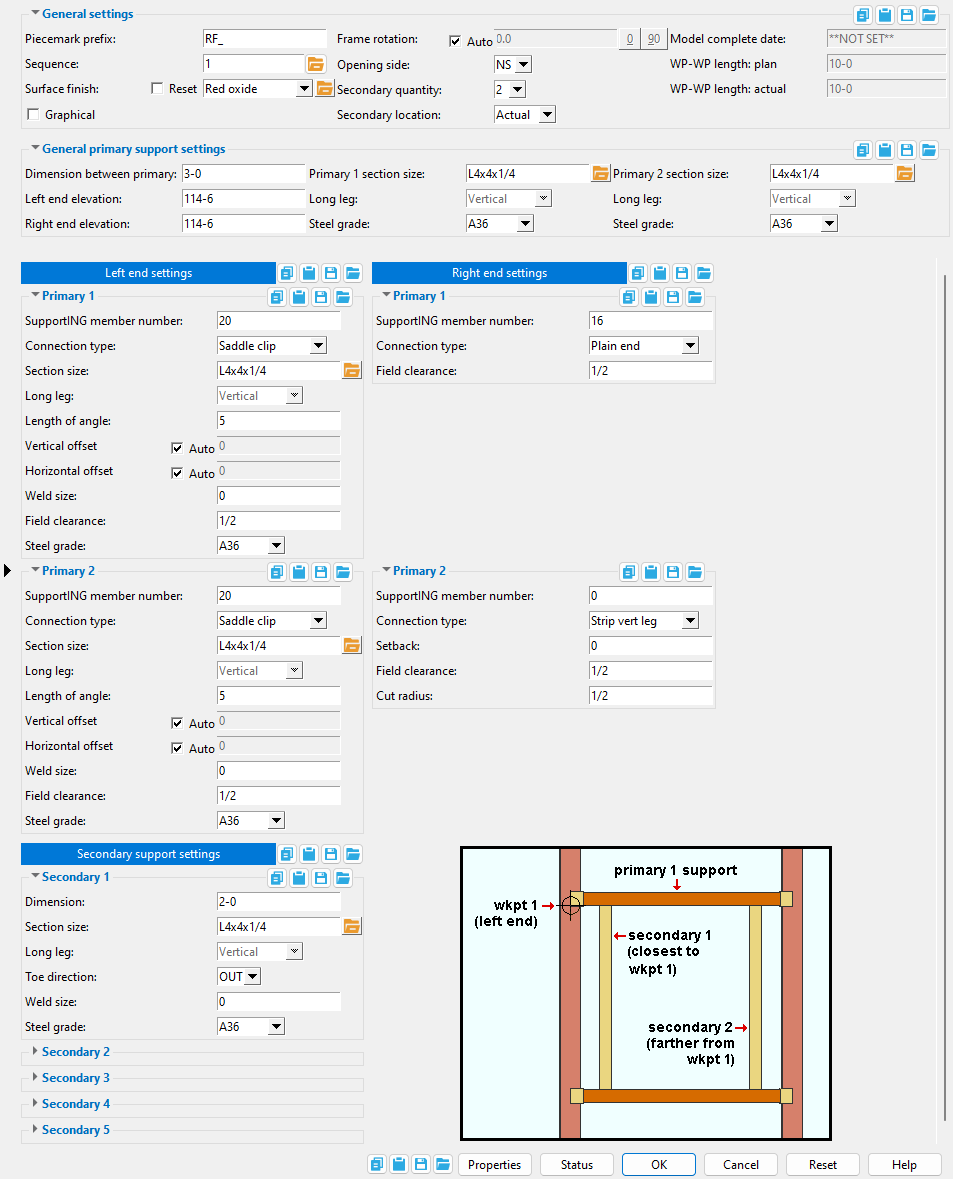
General settings
Piecemark prefix: Any characters that you want to begin the member piecemark that will be assigned to the roof frame that you are adding. The piecemark will be assigned when you press the " OK " button.
This applies to Add Roof Frame operations. For example, if you were to type in RF_ here, and this is the 89th member you have added, SDS2 piecemarking may add 89 after this prefix, thus assigning your new roof frame the piecemark RF_89 .
If you edit a roof frame and change its piecemark prefix, the old piecemark will continue to be used.
SDS2 piecemarking will not use the prefix entered here if the roof frame you are adding is exactly like another roof frame with a different prefix. The program will, instead, assign the new roof frame the same piecemark that was assigned to the previously added roof frame.
Sequence: Any sequence name from the Sequence Names setup list can be entered. Either type the sequence, or you can press the "file cabinet" browse button ( ![]() ) and double-click any sequence name that is on the list.
) and double-click any sequence name that is on the list.
Tip: If you want to add a new sequence so that it can be selected here, you should first increase the number of " Maximum sequences " that are available.
Surface finish: None or Sandblasted or Red oxide or Yellow zinc or Gray oxide or Blued steel or Galvanized or Duplex Coating or Undefined 1 or Undefined 2 or Undefined 3 or Red oxide 2 or Any user added surface finish. This affects the colors of Solid members on erection views in the Drawing Editor . This also sets the color when Output material color is set to Surface finish for a VRML Export or a DWG/DXF Export. The Color (not Surface finish) sets the color of this material in Modeling .
| sand blasted | red oxide | yellow zinc | user surface finish 1 |
| gray oxide | blued steel | galvanized | user surface finish 2 |
To assign a different surface finish, you can drop-down the current surface finish and select the one you want, or you can press the
browse button and double-click any surface finish that is on the list.
Auto ![]() or
or ![]()
If this box
is checked, the material surface finish follows what is set on the member level.
If the box
is not checked, the material surface finish can be changed to whatever is available in the list of surface finishes. If the surface finish changes from what the member level has set, the auto checkbox will be unchecked automatically. When the auto check box is unchecked, the member edit window shows an information tag which notifies the user that an attached material is not following what was set on the member level.
Note 1: Submaterial piecemarks can be split apart by surface finish. All surface finishes that do not have the Break Marks Material checked on can be applied to any like material with out the material splitting. If the Break Marks Material is checked on then only like materials with that specific surface finish can have the same piecemark, and because the submaterial marks differ so would the member's piecemark.
Note 2: When exporting a KISS file using "model" as the Data source surface finish data on the materials are compiled into the KISS download as follows, with a few exceptions (G=galvanized, N= none or sandblasted, P= others). Those exceptions are:
If the box for Finish routing in KISS export setup is set to a user routing
If the user has adjusted the Abbreviation for any of the default provided surface finishes
If you are using a user added surface finish
In these cases you will get what is provided in either the User routing, or the abbreviation field. For other exports it will always provide the abbreviation in the 'surface finishes' settings page.
Tip 1: Surface area is reported on the General Information window -- and this can be used to estimate the amount of coating required and its cost.
Tip 2: Changing Steel grade, Color, and Surface finish do not cause the plate to be regenerated. This means that, if you change those settings only, material fit operations such as a Fit Exact may optionally be preserved.
Report Writer: MemberMaterial.Material.SurfaceFinish
Setup: Surface Finish Settings
Graphical : ![]() or
or ![]() .
.
If the box is checked (
If the box is not checked (
Note:Add Material or Add Hole or Add Bolt does not change the member to graphical (
Frame rotation: ![]() Auto or .
Auto or . ![]() Auto . This is the rotation around the primary 1 support .
Auto . This is the rotation around the primary 1 support .
'
'
Opening side: NS or FS . This sets the location of the primary 2 support with respect to the primary 1 support. Two work points position the primary 1 support's location. The 1st point located sets the left end of the primary 1 support.
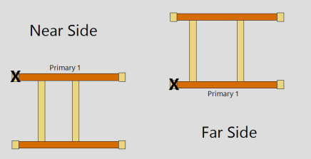
' NS ' places the opening to the near side of the primary 1 support. This means that the primary 2 support will be to the near side of the primary 1 support. The toe(s) of a channel or angle primary 1 support will point FS, away from the opening. The toe(s) of a channel or angle primary 2 support will point NS, also away from the opening.
' FS ' places the opening to the far side of the primary 1 support. This means that the primary 2 support will be to the far side of the primary 1 support. The toe(s) of a channel or angle primary 1 support will point NS, away from the opening. The toe(s) of a channel or angle primary 2 support will point FS, also away from the opening.
Related settings: The approximate size of the opening is the " WP-WP length: actual " by the " Dimension between primary ."
Secondary quantity: 0 or 1 or 2 or 3 or 4 or 5 .
' 0 ' results in a roof frame that has only a primary 1 support .
' 1 ' or ' 2 ' or ' 3 ' or ' 4 ' or ' 5 ' results in a roof frame that has both a primary 1 support and a primary 2 support . The number specified is the number of secondary supports.
Secondary location: Actual or Plan .
' Actual ' sets secondary support " Dimensions " to be measured in the same plane as the slope of the roof frame.
' Plan ' sets secondary support " Dimensions " to be measured in the plane of a plan view.
Model complete date: read-only .. The " Model completed " status of this member can be set using Update Attributes . You cannot set the " Model complete date " here, on this window.
' **NOT SET** ' indicates that this window is fully editable.
' month day year ' indicates that all fields on this window are in a disabled , read-only state due to the " Model completed " date having been set on this member, using Update Attributes , not necessarily on the reported date.
Also see: " Model complete date "
WP-WP length plan: read-only . The work point-to-work point distance (in the primary dimension " Units ") spanned by the roof frame's primary 1 support workline in a plan view, ignoring elevation. This distance is calculated from the X and Y (but not Z) global coordinates of the work points located when the roof frame was added .
Note: If the roof frame's primary 1 support is sloped out of the plan view elevation, the distance reported here will not be the actual work point-to-work point length, but rather the length of that support as measured at a single elevation.
WP-WP length: actual: Read-only . The actual length of this roof frame's primary 1 support workline (in the primary dimension " Units "). This distance is calculated from the X and Y and Z global coordinates of the work points located when the roof frame was added .
General primary support settings
Dimension between primary: The distance (in the primary dimension " Units " or other units ) from the inside face of primary support 1 to the inside face of primary support 2 . The inside faces are the faces of the primary supports that look inward, toward the roof frame opening. Primary support 1's inside face looks toward the primary 2 support. Primary support 2's inside face looks toward primary support 1.
|
d = dimension between primary |
Channel and angle supports are toed away from the opening. The opening-side faces of channel and angle supports are the heels of the channels or angles. The roof frame " Opening side " can be to the ' NS ' or ' FS ' of the primary 1 support.
Left end elevation: The elevation (in the primary dimension " Units " or other units ) of the 1st work point that was located.
|
To determine the left-end elevation on a roof frame in the 3D model, invoke Construction Line Add or a similar tool, select EXPT as the Locate option, then move the point location target to the work point at the left end of a roof frame and reference the Z coordinate reported in the X-Y-Z display . |
Unlike a beam, column or brace, the left-end work point of a roof frame is the 1st point that was located when the roof frame was added.
Right end elevation: The elevation (in the primary dimension " Units " or other units ) of the 2nd work point that was located.
To discover the right-end elevation on a roof frame in the 3D model, invoke Construction Line Add or a similar tool, select EXPT as the Locate option, then move the point location target to the work point at the right end of a roof frame and reference the Z coordinate reported in the X-Y-Z display .
Unlike a beam, column or brace, the right-end work point of a roof frame is the 2nd point that was located when the roof frame was added.
Primary 1 section size: angle , channel , HSS/TS are some acceptable shapes for the primary 1 support on a roof frame custom member. Other material types may also work.
|
Some Acceptable Material Types,
Roof Frame Primary 1 |
 |
To enter a section size: Either type in the section size that you want, or press the "file cabinet" browse button (
) and double-click any section that is listed. Validation only lets you enter a material that is listed in the local shape file . Also, if you enter a section size that is not available , validation opens a yes-no dialog with the warning, " The section size is not available from suppliers. Are you sure you want to use it? "
Primary 1 support material is placed so that its inside longitudinal face aligns with the two located work points . The inside face of the primary 1 support material faces the " Opening side " and looks toward the primary 2 support. The left end of the primary support 1 is the roof frame's 1st located work point .
Long leg: Horizontal or Vertical . This applies when an angle with unequal legs has been entered as the " Primary 1 section size ."
' Horizontal ' orients the long leg of the angle horizontally.
' Vertical ' orients the long leg of the angle vertically.
Steel grade: A36 or A572 or etc. The steel grade for the " Primary 1 section size " entered above.
Setup: The list of steel grades that are shown on the list box (
) for this field originate from the steel grade table at Home > Project Settings > Job that matches the material type of the primary 1 section. For example, if the primary 1 section is a channel, the list box is populated with steel grades from Home > Project Settings > Job > Channel Grades . For an angle primary 1 section, the list box is populated by steel grades from Home > Project Settings > Job > Angle Grades . HSS/TS are some acceptable shapes for the primary 2 support on a roof frame custom member. Other material types may also work. In order to get a primary 2 support, the " Secondary quantity " must be a number greater than 0.
Primary 2 section size: angle , channel , HSS/TS are some acceptable shapes for the primary 2 support on a roof frame custom member. Other material types may also work. In order to get a primary 2 support, the " Secondary quantity " must be a number greater than 0.
Some Acceptable Material Types,
Roof Frame Primary 2To enter a section size: Either type in the section size that you want, or press the "file cabinet" browse button (
Tip: If you don't want a primary 2 support, set the " Secondary quantity " to ' 0 '.
Long leg: Same as " Long leg " for the primary 1 support, except that this applies to the " Primary 2 section size ."
Steel grade: Same as " Steel grade " for the primary 1 support, except that this applies to the " Primary 2 section size ."
Primary 1 / Primary 2
A roof frame can take four connections. The primary 1 support has a left- and right-end connection. The primary 2 support also has a left- and right-end connection. The instructions that follow apply to all four connections. Supporting member number: 0 or a whole number ( member number ).
' 0 ' indicates that there is no supporting member for this end of the primary 1 or primary 2 support.
A ' number ' identifies the member number of the member that supports this end of the primary 1 or primary 2 support. Information from this supporting member is read from, for example, to determine how the " Field clearance " is applied to a connection.
Connection type: Plain end or Saddle Clip or Strip vertical leg .
' Plain end ' permits you to apply a ' Field clearance '. No other connection settings are available for a ' Plain end '.
' Saddle clip ' allows you to enter an angle " Section size " a " Length of angle " and various other settings.
' Strip vertical leg ' cuts the vertical leg of an angle so that the horizontal leg can rest on the supporting member (" Supporting member number "). You can enter a " Setback " a " Field clearance " and a " Cut radius ."
Section size: Any angle whose section size is listed in the local shape file . This applies when the " Connection type " is ' Saddle clip '.
To enter a section size: You can type in the angle section size that you want, or you can press the "file cabinet" browse button (
Long leg: Horizontal or Vertical . This applies when an angle with unequal legs has been entered as the " Section size " for the saddle clip connection.
' Horizontal ' orients the long leg of the angle horizontally. If the roof frame is sloping, it orients the long leg in the same plane as the roof frame.
' Vertical ' orients the long leg of the angle vertically. If the roof frame is sloping, it orients the long leg perpendicular to the plane of the roof frame.
Length of angle: The distance (in the primary dimension " Units " or other units ) between the outside edges of the saddle clip angle whose " Section size " is specified above. In other words, this is the length which that angle will be cut to.
Vertical offset:
In this example, the " Vertical offset " is equal to the leg thickness of the saddle clip, thus placing the bottom of the saddle clip flush with the top flange of the supporting beam. '
'
The vertical offset dimension runs perpendicular to the plane of the roof support custom member, vertically if the Left end elevation and Right end elevation of the roof frame are equal and the Frame rotation is ''. """""" 0
Horizontal offset:
'
'
The horizontal offset dimension runs perpendicular to the length of the roof frame's primary supports, whose longitudinal direction is determined by the two located work points .
Weld size: The fillet weld size for shop welding the primary support to the saddle clip. Entering ' 0 ' removes the saddle clip welds.
Setback: The positive (+) or negative (-) distance (in the primary dimension " Units " or other units ) that you want the end of the support to be set back from its setback-equals-zero location. This applies when the " Connection type " is ' Strip vertical leg '.
Tip: Adjust the " Setback " together with the " Field clearance " to properly fit the ' Strip vertical leg ' connection to the " Supporting member number ." ' 0 ' sets the end of the primary support at the center of the supporting member (" Supporting member number ").
' A positive (+) distance ' sets back the end of the primary support, thus shortening the primary support.
' A negative (-) distance ' extends the end of the primary support, thus shortening the primary support.
Field clearance: A distance (in the primary dimension " Units " or other units ). The precise definition of " Field clearance " depends on the " Connection type ."
For a ' Plain end ' connection, the " Field clearance " is the distance between the " Supporting member number " and the primary support. 
For a ' Saddle clip ' connection, the " Field clearance " is the distance between the " Supporting member number " and the vertical leg of the saddle clip. 
For a ' Strip vertical leg ' connection, the " Field clearance " is the distance between the " Supporting member number " and the vertical leg of the primary support when the " Setback " is equal to ' 0 '. Cut radius: The radius of the cut that is made to this end of the primary support when the " Connection type " is ' Strip vertical leg '. This distance may be entered in the primary dimension " Units " or other units .
Steel grade: A36 or A572 or etc. This is the connection material steel grade when the " Connection type " is ' Saddle clip '. It applies to the " Section size " entered above.
Setup: If the grade of steel you want is not shown on the list box (
Secondary 1 /
Dimensions: A distance (in the primary dimension " Units " or other units ). Depending on the leaf you are in, this is the dimension to support 1 or dimension to support 2 or dimension to support 3 or etc. Whether this distance is measured as an actual dimension or a plan dimension depends on the choice made to " Secondary location ."
Dimension to support 1 Distance from the 1st work point located to support 1. Dimension to support 2 The distance from support 1 to support 2. Dimension to support 3 The distance from support 2 to support 3. Dimension to support 4 The distance from support 3 to support 4. Dimension to support 5 The distance from support 4 to support 5.
The 1st work point located establishes the left end of the roof frame. Support 1 is the left most support, support 2 is the next left most support, and so on ....
Measurements to and from a support are to/from the left most edge or face of that support.Section size: Angle , channel , HSS/TS are some acceptable shapes for a secondary support on a roof frame custom member. Other material types may also work.
Some Acceptable Material Types,
Secondary SupportsTo enter a section size: Either type in the section size that you want, or press the "file cabinet" browse button (
Long leg: This applies when an angle with unequal legs has been entered as the " Section size " for the secondary support.
' Horizontal ' orients the long leg of the angle horizontally. If the roof frame is sloping, it orients the long leg in the same plane as the roof frame.
' Vertical ' orients the long leg of the angle vertically. If the roof frame is sloping, it orients the long leg perpendicular to the roof frame.
Toe direction: IN or OUT . This applies when the " Section size " for the secondary support is an angle or a channel.
' IN ' points the toe(s) of the channel or angle toward the left end of the roof frame. That is, it points the toe(s) toward the 1st work point located .
' OUT ' points the toe(s) of the channel or angle away from the left end of the roof frame. That is, it points the toe(s) away from the 1st work point located.
Weld size: The fillet weld size for shop welding the secondary support to the primary 1 support and to the primary 2 support . Entering ' 0 ' removes the secondary support welds.
The " Weld size " entered here applies to both ends of the secondary support. Only one end in shown in this example. One end of a secondary support frames to primary support 1. The other end frames to primary support 2. Steel grade: A36 or A572 or etc. The steel grade for the secondary support " Section size " entered above.
Setup: The list of steel grades that are shown on the list box (
Copy, Paste, Save, Load buttons:
- The position of these "form" buttons on the window tells you what settings they apply to. Click here for more information.
- You can
Copy the settings on this window, then
Paste those settings to a different edit window of the same type.
- You can
Save the settings on this window to a file stored in a global folder that is used by your current version of SDS2. Give the file a name that will help other users identify its purpose. You can
- When editing multiple windows at the same time, Paste and Load replace mixed entries to a single field with a single entry. Copy and Save ignore fields with mixed entries, treating them as if they have no entry or do not exist.
Properties opens the Edit Properties window, on which you can make entries to custom properties. If your current Job was set to use a legacy flavor when it was created, the window that opens is named Custom Properties , not Edit Properties.
Tip: The Edit Properties window can also be used to read
Tip: The Member Properties command is an alternative to this button. It opens the Edit Properties window directly, without your first having to open a member edit window.
Status opens the Member Status Review window, which can give you additional information about the member, and which you can use to enter status information or designate a member as an existing member.
Note: This button shows
if one or more Repeat check boxes on the Member Status Review window do not match the checked-unchecked state of same-named fields in User and Site Options > Site > Member status items to copy/repeat. On the Status Review window, the fields that do not match User and Site Options are plotted in red .
OK (or the Enter key) closes the edit window and saves any changes you have made on the window to the member file.
Solids on OK: If the appropriate choice is made to User and Site Options > Modeling > Automatically process after modeling operation, then this member will automatically be regenerated (Create Solids will take place) after your press OK. Otherwise, you will have to manually Process and Create Solids in order for changes you made on this window to be fully updated in the 3D model.
Change all: If you Edit Member (one member only) and make a change that potentially triggers the Do you want to change all ... dialog and the 3D model contains more than one member of the same type that has the same piecemark as the member you changed, a yes-no dialog opens. On it is the question, Do you want to change all (members with this piecemark). Press the Yes button to change all the members; press the No button to change only this member.
Cancel (or the Esc key or the
button) closes the edit window without saving any changes that you have made. Cancel does not undo a Detail Member operation.
Note: If you opened this window while adding a member, Cancel brings you back to the work point location step of adding a member.
Tip: Any time you use Edit Member just to review a member (and you do not want to set the defaults for to-be-added members), the best way to close this window is to Cancel.
Reset undoes any changes made since you opened this window.
Exception: Reset does not undo changes made using the Add View, Delete View, Detail Member, and View detail buttons.
- Add Roof Frame
- Custom members (topic)
- Roof Frame Setup (defaults for 1st roof frame added) (
 )
)

